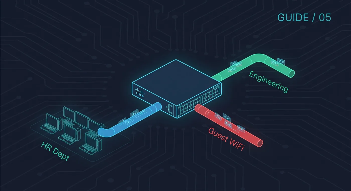
A VLAN splits one physical switch into separate logical networks. Students, staff and servers can share the same hardware but stay in different broadcast domains, which is better for both performance and security.
Want every command on one page? Cisco Networking Guide · $14.99View on Gumroad
1. Create the VLANs
Switch(config)# vlan 10
Switch(config-vlan)# name STUDENTS
Switch(config-vlan)# vlan 20
Switch(config-vlan)# name STAFF
2. Put access ports into a VLAN
Switch(config)# interface fa0/1
Switch(config-if)# switchport mode access
Switch(config-if)# switchport access vlan 10
3. Build a trunk between switches
Switch(config)# interface gi0/1
Switch(config-if)# switchport mode trunk
Switch(config-if)# switchport trunk allowed vlan 10,20
On some switch models you must first run switchport trunk encapsulation dot1q. If the command is rejected, your switch only supports 802.1Q and does not need it.
4. Let VLANs talk to each other
Different VLANs need a router. The simplest lab method is router-on-a-stick: one trunk link to the router, with a sub-interface per VLAN.
Router(config)# interface g0/0.10
Router(config-subif)# encapsulation dot1Q 10
Router(config-subif)# ip address 192.168.10.1 255.255.255.0
Remember to run no shutdown on the physical interface g0/0.
5. Verify
show vlan brief
show interfaces trunk
If two hosts in the same VLAN cannot ping, check the access port VLAN first. If hosts in different VLANs cannot ping, check the trunk and the sub-interface gateway.